


")
")

")
")

")
")
")
")

")
")

")
")

")
")
")
")

")
")
")
")

Address:
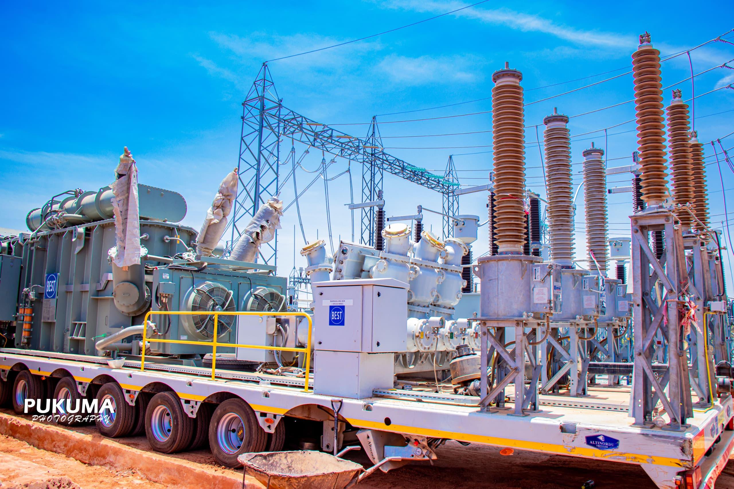
DAMATURU TRANSMISSION SUBSTATION YOBE STATE
- Project Main Objective
- Supply and Installation of 1x60MVA, 132/33kV (Mobitra) and Installation of associated 2x33kV feeder bays at Damaturu 330/132/33kV Transmission Substation in Yobe State.
- Project Scope
The scope of the contract covers the design, supply, installation and commissioning of
HV and MV equipment as listed below;
- Mobile Power Transformer 60/66 MVA, 132/33kV complete with transformer oil filled, primary and secondary bay equipment, Tripping unit, protection and other ancillaries including ET and more
- 36kV CB complete with support structure.
- 36kV DS complete with support structure
- 36kV DS with grounding blade complete with support structure
- 33kV VT (1/phase)
- 33kV CT (1/phase) 800/600/400/300/1/1/1/1/1/A
- Ur=30kV Surge arrester (1/phase)
Control and Protection Panels, as listed below
- Control and protection panel for 2x33kV outgoing Feeders
Galvanized Steel and Concrete Pole Structure
- 132kV Gantry for Mobitra
- Complete Concrete Pole structure for 33kV single busbar
- Complete Concrete Pole structure for 33kV Feeders
- Structures for 132kV and 33kV Post-type Insulator
- Structures for 33 kV Instrument Transformer
Earthing System
- Extension of Stranded bare galvanized steel 75X12 mm Flat/32mm diameter minimum GL Flat or MS Rod
- Stranded bare galvanized steel 50X10 mm GL Flat
- Insulated copper conductor 70 mm²
- Grounding rod 40mm diameter 3m long/40mm dia.3m.long GL pipe
- Grounding fusion connectors
- Grounding mechanical connectors
Over Head Connections
- Extension of Hardware/fittings for shield wire and lightning spikes
- 132 kV and 33kV suspension/tension string fittings
- Porcelain String Insulators
- 132kV and 33kV post-type insulators
- conductor for 33kV busbar and overhead connection (1x800mm2 )
- Conductor for overhead connections 132kV (1x800mm2)
- Busbar and equipment connectors, hardware, fittings and accessories
Accessories and Anciliary Materials;
- Junction box for Voltage Transformer
- Junction box for Current Transformer
MV and LV cables, as listed below;
- Control cables – 12C x 2.5 mm²
- Control cables – 4C x 4 mm²
- Low Voltage Power Cables – 4C x 120 mm²
- Wiring accessories, Cable Lug, Cable Belt, Ferrules e.t.c
The Single Line Diagram depicting the proposed 1x60MVA Mobitra and 2x33kV outgoing feeders as enclosed in the bidding document shall be used as a reference to identify all the needed civil works and electromechanical works. Seak Risk Management shall design and construct according to IEC standard and TCN specification to provide a complete functional installation as follows;
- Soil test
- Earthworks; removal of top soil to necessary depth, filling, leveling and compaction
- Foundation works where necessary
- Foundation integrity test
- Installation of complete Earth grid and connections (electrode system)
- Erection of galvanized steel and concrete pole structures where necessary
- Erection of HV and MV equipment
- Installation of all Overhead Connections; insulators, conductors, clamps, suspension/tension string fittings
- Cable concrete trenches and imbedded ducts with pulling boxes and cable pits where necessary.
- Installation of MV and LV Cables
- Installation of Control and Protection Panels
- Installation of accessories and ancillary system
- Final termination of conductors, cables and earthing system
- Consolidation and gravelling
- Other related works to make a complete installation.


")
")

")
")

")
")
")
")